This tutorial simulates a cross-country flight from Reid-Hillview (KRHV) to Livermore (KLVK) under Visual Flight Rules (VFR). Both airports are not included in the standard FlightGear package, therefore make sure that in the Launcher you have enabled the option Download scenery automatically, which is in the Settings tab.
I’ll assume that you are happy taking off, climbing, turning, descending and landing in FlightGear. If not, have a look at the tutorials in chapters 7 (Tutorials) and 8 (A Basic Flight Simulator Tutorial). This tutorial is designed to follow on from them and provide information on some of the slightly more complicated flight systems and procedures.
A quick disclaimer. I fly microlights rather than Cessnas in real life. Most of this information has been gleaned from various non-authoritive sources. If you find an error or misunderstanding, please let me know. Mail me at stuart_d_buchanan -at- yahoo.co.uk.
I’d like to thank the following people for helping make this tutorial accurate and readable: Benno Schulenberg, Sid Boyce, Vassilii Khachaturov, James Briggs.
Before we begin, we need to plan our flight. Otherwise we’ll be taking off not knowing whether to turn left or right.
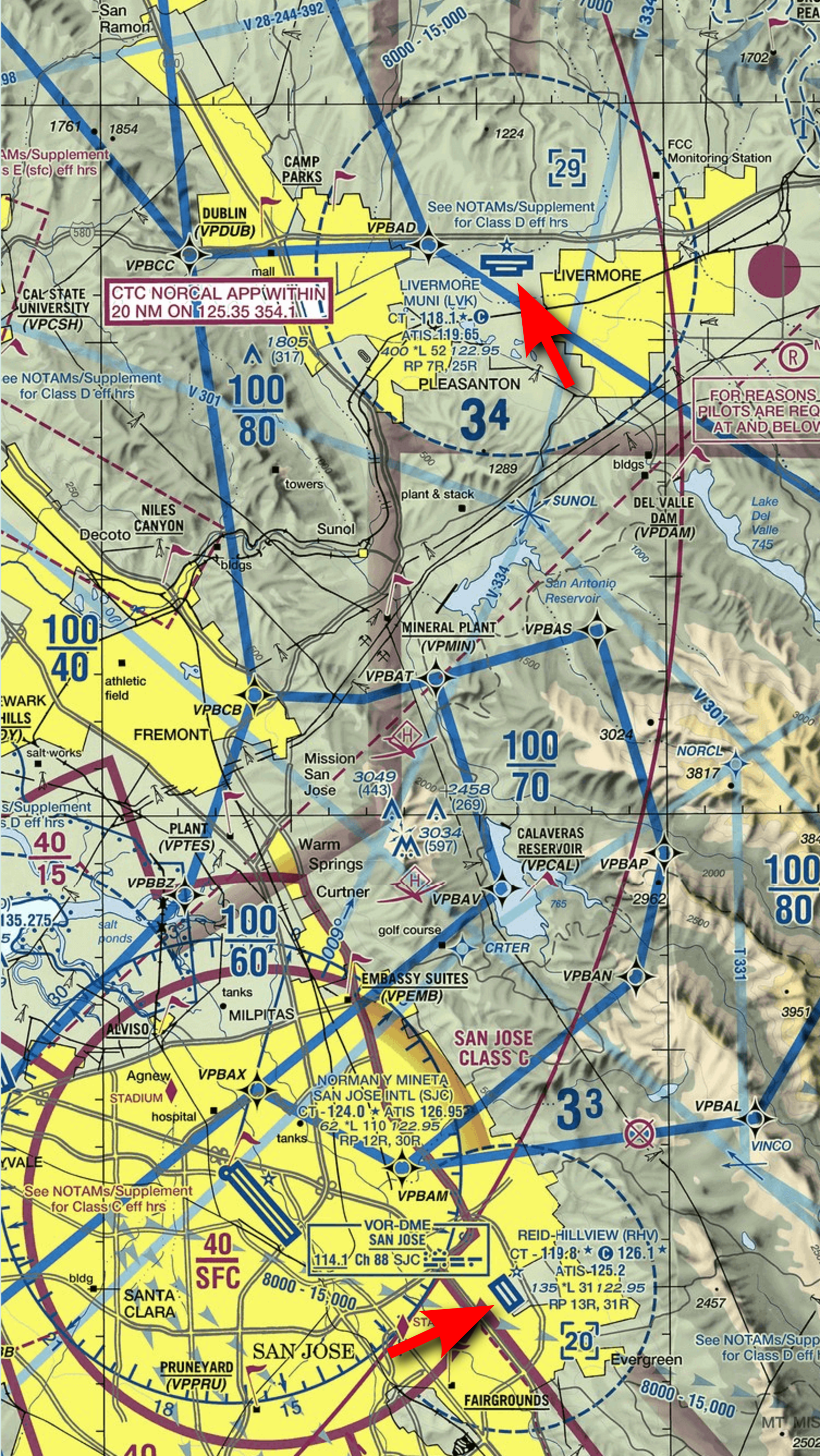
First, have a look at the Sectional for the area. This is an aeronautical map which shows airports, navigational aids, and obstructions. There are two scales of sectionals for VFR flight – the 1:500 000 sectionals themselves, and a number of 1:250 000 VFR Terminal Area Charts which cover particularly busy areas.
They are available from pilot shops, or on the web from various sources. You can access a Google-map style interface here:
Simple click “Flight Plan” and enter KRHV to “Departure” field. An extract from the chart is shown in Figure 9.2.
If you want a map of the entire area showing exactly where the plane is, you can use Atlas. This is a moving-map program that connects to FlightGear. See Section 6.3 for details.
An even simpler option is to use “Phi”, which is a map in the browser. Just run FlightGear
with the command line option --httpd=8080 and then in the simulator choose
Equipment → Map (opens in browser) from main menu.
So, how are we going to fly from Reid-Hillview to Livermore?
We’ll be taking off from runway 31R at KRHV. KRHV is the ICAO code for Reid-Hillview airport, and you can find them in Launcher in Location tab. (It is marked on the sectional as RHV for historic reasons. To get the ICAO code, simply prefix a “K”.)
The 31 indicates that the magnetic heading of the runway is around 310 degrees, and the R indicates that it’s the runway on the right. As can be seen from the sectional, there are two parallel runways at KRHV. This is to handle the large amount of traffic that uses the airport. Each of the runways can be used in either direction. Runway 31 can be used from the other end as runway 13. So, the runways available are 13R, 13L, 31R, 31L. Taking off and landing is easier done into the wind, so when the wind is coming from the North West, runways 31L and 31R will be in use. The name of the runway is written in large letters at the beginning and is easily seen from the air.
Once we take off we’ll head at 350° magnetic towards Livermore (KLVK). We’ll fly at about 3500 ft about sea-level. This puts us at least 500 ft above any terrain or obstructions like radio masts on the way.
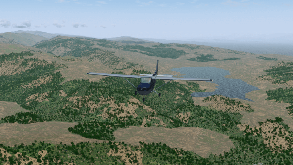
We’ll fly over the Calaveras Reservoir then the San Antonio Reservoir. These are both large bodies of water and we can use them as navigation aids to ensure we stay on the right track.
Once we get about 10 miles out of Livermore (above the San Antonio Reservoir), we’ll contact the Livermore Air Traffic Control (ATC) to find out where we should land. We’ll then join the circuit and land.
OK, we know where we’re going and how we’ll get there. Time to get started.
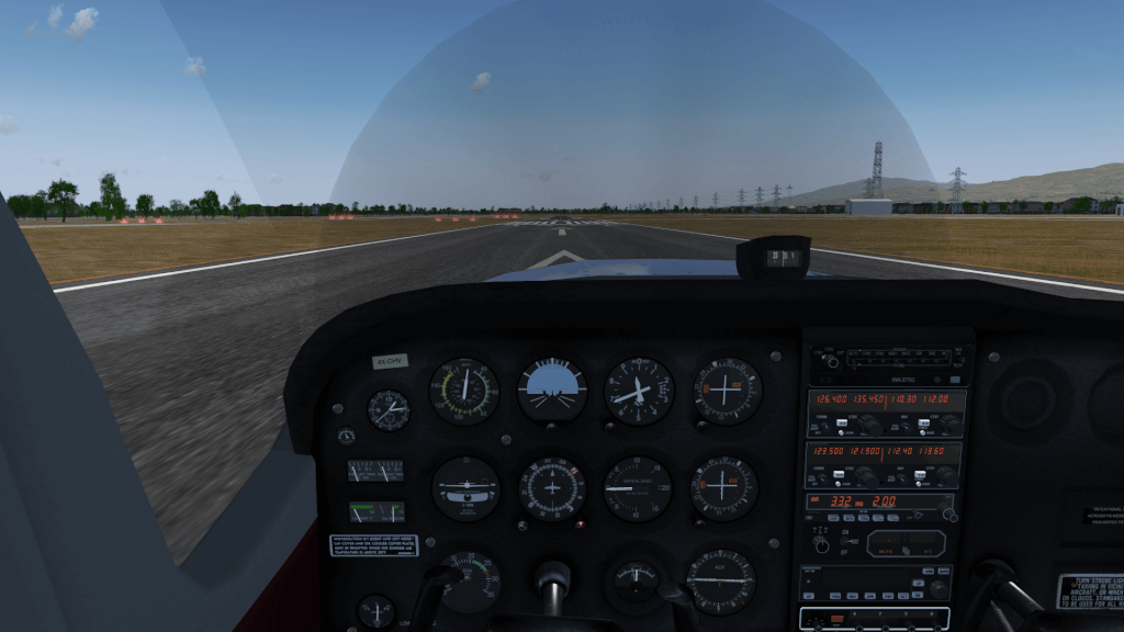
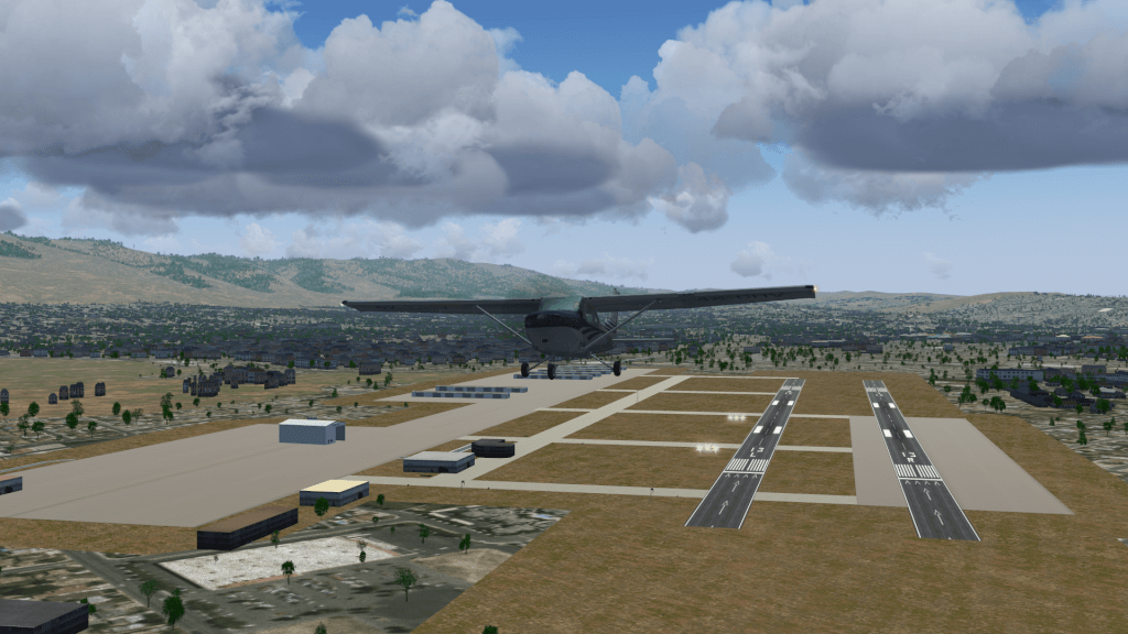
Start FlightGear using the launcher (or command-line if you prefer). We want to use a C172P and take off from runway 31R at Reid-Hillview of Santa Clara County (KRHV). Dawn is a nice time to fly in California.
If you want, you can fly in the current weather at KRHV (which is recommended to be able to listen the ATIS.) To do this, in the Launcher, go to the Environment tab and check the Real-world weather option.
Before we take off, we need to preflight the aircraft. In the real world, this consists of walking around the aircraft to check nothing has fallen off, and checking we have enough fuel. If you want, you can do this by selecting Walker → Toggle Walker outside from the main menu.
However, in our case, we’ll take the opportunity to check the weather, set our altimeter and pre-set things that are easier to do when you’re not flying.
The weather is obviously important when flying. We need to know if there is any sort of cross-wind that might affect take-off, at what altitude any clouds are (this is a VFR flight – so we need to stay well away from clouds at all times), and any wind that might blow us off course.
We also need to calibrate our altimeter. Altimeters calculate the current alititude indirectly by measuring air pressure, which decreases as you ascend. However, weather systems can affect the air pressure and lead to incorrect altimeter readings, which can be deadly if flying in mountains.
Conveniently, airports broadcast the current sea-level pressure along with useful weather and airport information over the Automatic Terminal Information Service (ATIS). This is a recorded message that is broadcast over the radio. However, to listen to it, we need to tune the radio to the correct frequency.
The ATIS frequency is displayed on the sectional (look for “ATIS” near the airport), but is also available from within FlightGear. To find out the frequencies for an airport (including the tower, ground and approach if appropriate), use the AI → ATC Services in Range menu. Then, in the dialog box, click the button with the ICAO code of our airport, i.e. KRHV. The various frequencies associated with the airport are then displayed. Duplicates indicate that the airport uses multiple frequencies for that task, and you may use either.
Either way, the ATIS frequency for Reid-Hillview is 125.2 MHz.
We now need to tune the radio. The radio is located in the Radio Stack to the right of the main instruments. There are actually two independent radio systems, 1 and 2. Each radio is split in two, with a communications (COMM) radio on the left, and a navigation radio (NAV) on the right. We want to tune COMM1 to the ATIS frequency.
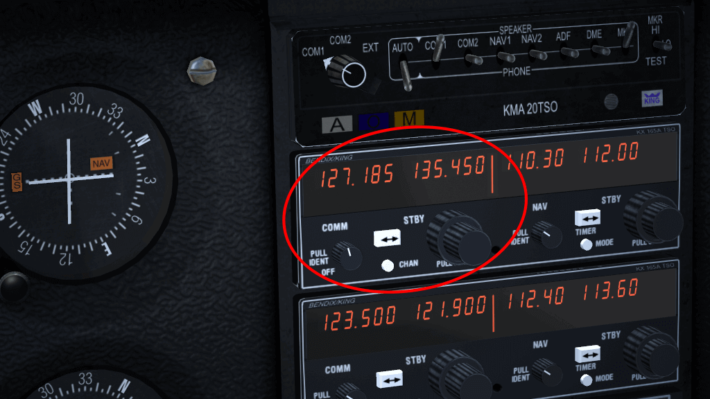
The radio has two frequencies, the active frequency, which is currently in use, and the standby frequency, which we tune to the frequency we wish to use next. The active frequency is shown on the left 6 digits, while the standby frequency is shown on the right. We change the standby frequency, then swap the two over, so the standby becomes active and the active standby. This way, we don’t lose radio contact while tuning the radio.
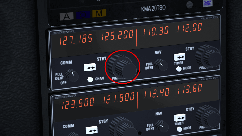
To change the frequency, use the mouse wheel on the black knob below the standby frequency (highlighted in the Figure 9.5), just to the right of the “STBY”. Turning the mouse wheel over the small (inner) knob changes the decimal point (kHz), and turning the wheel over the large (outer) knob changes the number before the decimal place (MHz). Turnning the wheel in both ways – you will see the values go up and down. Alternatively, you can click each knob. Left click mouse button increasing the frequency, and middle click decreasing.
As for the COMM radio, note that the frequency before the decimal point (MHz) can be set in the range from 118 to 136, in 1 MHz step. However, the frequency after the decimal point can work in two standards, the older one with a spacing of 25 kHz , or the new one with a spacing of 8.33 kHz. The default is 8.33 kHz spacing, giving you more frequencies to choose from. If you want you can switch the radio between 25 kHz and 8.33 kHz spacing, just hold down the Shift key and click the little knob. When you look closely, you will notice that a small, inner knob is pushed in.
If you are having difficulty clicking on the correct place, press Ctrl-c to highlight the hot-spots for clicking.
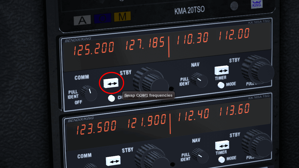
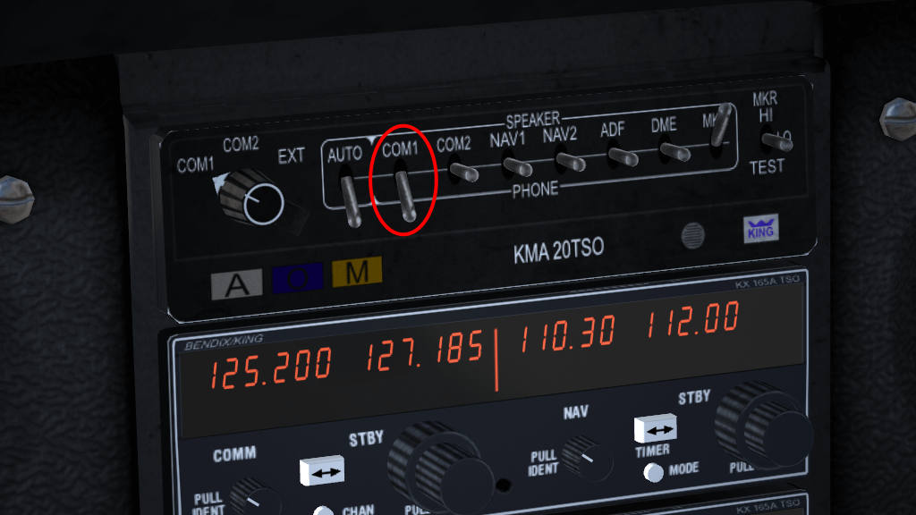
Once you have tuned the frequency to 125.2 MHz, press the white button with arrows, located between the words “COMM” and “STBY” to swap the active and standby frequencies (highlighted in Figure 9.6). After a second or so, you’ll hear the ATIS information. If you can’t hear ATIS, make sure the “COMM1” switch above the frequencies is in the Speaker or Phone position (see Figure 9.7).
Listen for the “Altimeter” setting. If you are not using real weather, the atmospheric pressure will depend on the weather conditions set, according to the selected weather scenario. Then listening to ATIS will be impossible. Therefore, to check the pressure, go to menu Environment → Weather. In the bottom of new window, there is a METAR (Meteorological Aerodrome Report) message with atmospheric pressure. If you don’t know how to read the METAR please use the “METAR Description” button.
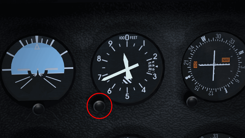
As you can see, the atmospheric pressure can be different every time. Therefore, we need to set the altimeter to the correct value. To do this, use the knob at the bottom left of the altimeter (circled in red in Figure 9.8), in the same way as you changed the radio frequency. Turning the knob changes the value in the little window on the right of the altimeter. You must set the same value as given by ATIS (or METAR). Notice that the altitude indicated by the altimeter is changing too.
The other way to set the altimeter is to match it to the elevation above sea-level of the airport. The elevation is listed on the sectional. For KRHV it is 133 ft. This means you can double-check the pressure value reported over ATIS.
As you may have noticed, the pressure on the Cessna altimeter can only be set in units of inHg. Fortunately, we fly in the USA, where ATIS also gives us the pressure in inHg . But when flying in Europe, for example, the pressure will be given in hPa. Then we have to convert hPa to inHg, or simply use the “METAR Description” window mentioned above. Another way is to use the menu Equipment → Instrument Settings, where you can set the pressure for the altimeter, both in hPa and inHg.
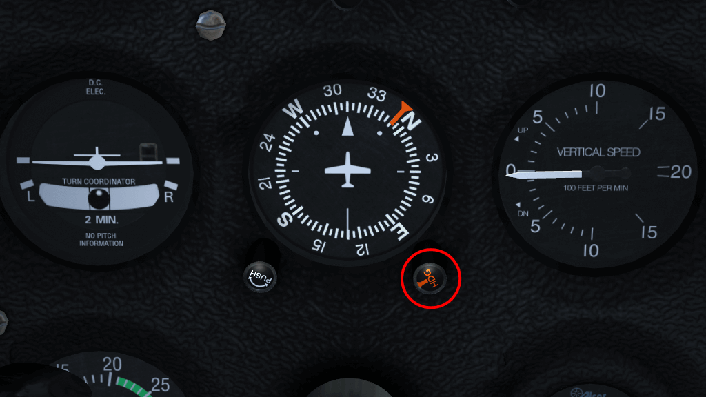
We will also take the opportunity to set the heading bug on the heading indicator to 350° – our bearing from KRHV to KLVK. To do this, use the amber knob on the heading indicator housing (highlighted in Figure 9.9), just as you’ve done before. For faster rotation, hold down the Shift key to increase the increment value by 5°. The value of 350° is just anti-clockwise of the labeled value of N (North – 000°).
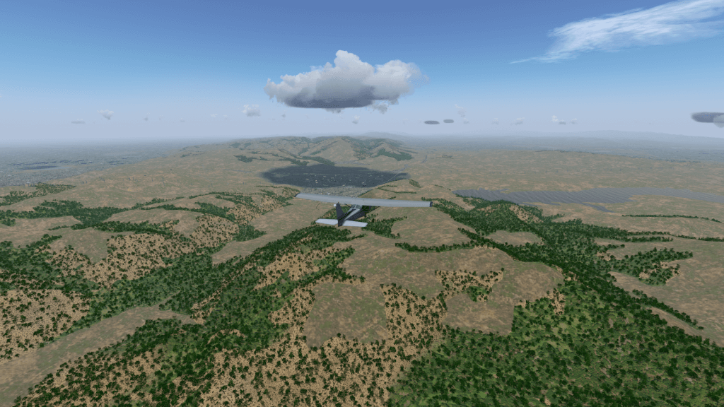
OK, now we’ve done that we can actually take off! In my case this usually involves weaving all over the runway, and swerving to the left once I’ve actually left the ground, but you’ll probably have better control than me. Once above 1000 ft, make a gentle turn to the right to a heading of 350°. As we’ve set the heading bug, it will be easy to follow. We’re aiming for a fairly prominent valley.
Continue climbing to 3500 ft at around 500-700 fpm. Once you reach that altitude, reduce power, level off to level flight and trim appropriately. Check the power again and adjust so it’s in the green arc of the RPM gauge. We shouldn’t run the engine at maximum RPM except during take-off.
OK, we’ve taken off and are on our way to Livermore. Now we can make our life a bit easier by using the autopilot and our plane more fuel efficient by tuning the engine. We’ll also want to check we’re on-course.
We can make our life a bit easier by handing some control of the aircraft over to “George” – the autopilot.
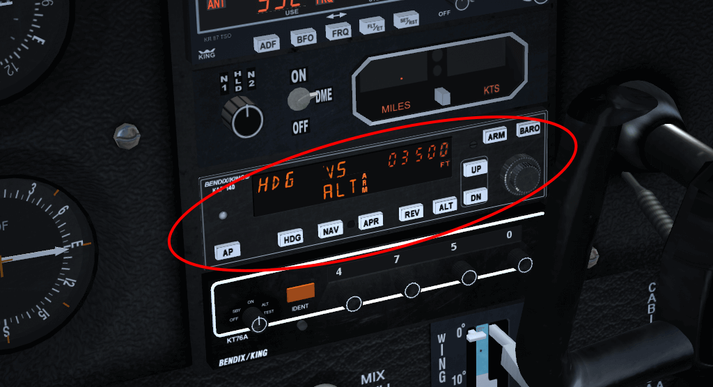
The autopilot panel is located towards the bottom of the radio stack (highlighted in Figure 9.11). It is easily distinguishable as it has many more buttons than the other components on the stack. It can work in a number of different modes, but we are only interested in one of them for this flight – HDG. As the names suggest, HDG will cause the autopilot to follow the heading bug on the heading indicator, which we set earlier.
To set the autopilot, press the AP button to switch the autopilot on, then press the HDG button to activate heading mode. While the autopilot is switched on, it will use the ailerons controls to keep the plane on the heading. You can change the heading bug, and the autopilot will maneuver appropriately. However, the autopilot doesn’t make any allowances for wind speed or direction, it only sets the heading of the airplane. If flying in a cross-wind, the plane may be pointed in one direction, but be travelling in quite another.
You should use the trim controls to keep a level flight. You can use the autopilot for this, but it is a bit more complicated.
Once the aircraft has settled down under the autopilot’s control, we can pay more attention to the outside world and higher level tasks.
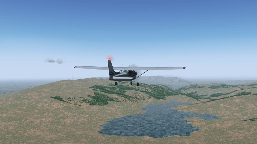
As we noted above, we’re going to be travelling over a couple of reservoirs. When you leveled off, the first (Calaveras) was probably right in front of you. You can use them to check your position on the map. If it looks like you’re heading off course, twist the heading bug to compensate.
As altitude increases, the air gets thinner and contains less oxygen. This means that less fuel can be burnt each engine cycle. The engine in the C172 is simple and doesn’t automatically adjust the amount of fuel to compensate for this lack of oxygen. This results in an inefficient fuel burn and a reduction in power because the fuel-air mixture is too “rich”. We can control the amount of fuel entering the engine every cycle using the mixture control. This is the red lever next to the throttle (Figure 9.14). By pulling it out, we “lean” the mixture. We don’t want the mixture too rich, nor too lean. Both these conditions don’t produce as much power as we’d like. Nor do we want it perfect, because this causes the fuel-air to explode, rather than burn in a controlled manner, which is a quick way to trash an engine.
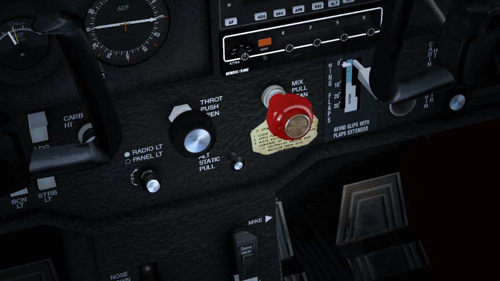
The mixture is controlled by the red lever to the right of the yoke. You may need to pan your cockpit view to see it.
To pan the cockpit view, hold down the right mouse button. Moving the mouse now pans the view. Once you can see the mixture lever clearly, release the right mouse button.
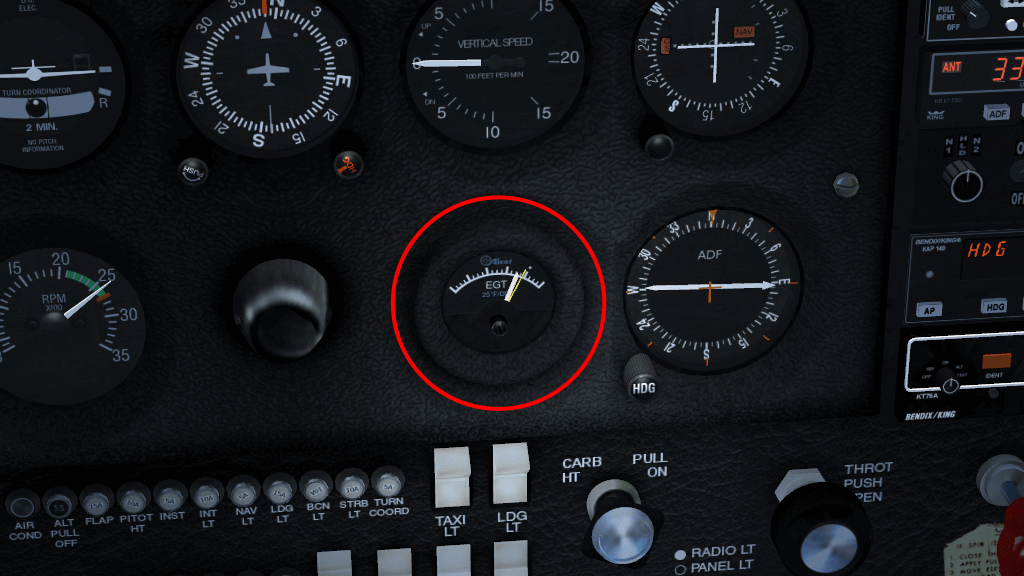
Pull the mixture lever out slowly (use Ctrl-c to see the hot spots), leaning the mixture. As you do so, you’ll see various engine instruments (on the left of the panel) change. Fuel flow will go down (we’re burning less fuel), EGT (Exhaust Gas Temperature) will go up (we’re getting closer to a “perfect mixture”) and RPM will increase (we’re producing more power). Pull the mixture lever out until you see the EGT go off the scale, then push it in a bit (see Figure 9.15). We’re now running slightly rich of peak. While at 3500 ft we don’t need to lean much, at higher altitudes leaning the engine is critical for performance.
Once you reach the second reservoir (the San Antonio Reservoir), we need to start planning our descent and landing at Livermore. Landing is a lot more complicated than taking off, assuming you want to get down in one piece, so you may want to pause the simulator (press p) while reading this.
In the Real World, we’d have been in contact with Air Traffic Control (ATC) continually, as the bay area is quite congested in the air as well as on the ground. ATC would probably provide us with a “flight following” service, and would continually warn us about planes around us, helping to avoid any possible collisions. The FlightGear skies are generally clear of traffic, so we don’t need a flight following service. If you want to change the amount of traffic in the sky, you can do so from the AI menu.
Livermore Airport is Towered (towered airports are drawn in blue on the sectional), so we will need to communicate with the tower to receive instructions on how and where to land.
Before that, we should listen to the ATIS, and re-adjust our altimeter, just in case anything has changed. This is quite unlikely on such a short flight, but if flying hundreds of miles, it might make a difference. To save time when tuning radios, you can access the Radio Frequencies dialog from the Equipment → Radio Settings menu. The Livermore ATIS frequency is 119.65 MHz.
An ATIS message also has a phonetic letter (Alpha, Bravo, … Zulu) to identify the message. This phonetic is changed each time the recorded message is updated. When first contacting a tower, the pilot mentions the identifier, so the tower can double-check the pilot has up to date information.
Besides the altitude and weather information, the ATIS will also say which runway is in use. This is useful for planning our landing. Normally, due to the prevalent Westerly wind, Livermore has runways 25R and 25L in use.
Once you’ve got the ATIS, tune the radio to Livermore Tower. The frequency is 118.1 MHz . Depending on the level of AI traffic you have configured on your system, you may hear Livermore Tower talking to other aircraft that are landing or departing.
Once the frequency goes quiet, press the ’ key. This will bring up the ATC menu. Click on the radio button on the left to select what you wish to say (you only have one option), then click OK.
Your transmission will be displayed at the top of the screen. It will indicate who you are (type and tail number), where you are (e.g. 6 miles south), that you are landing, and the ATIS you have.
After a couple of seconds, Livermore Tower will respond, addressing you by callsign and telling you what runway to use, which pattern is in use and when to contact them, for example:
“Golf Foxtrot Sierra, Livermore Tower, Report left downwind runway two five left.”
To understand what this means, we’ll have to describe the Traffic Pattern.
With the number of aircraft flying around, there have to be standard procedures for take-off and landing, otherwise someone might try to land on-top of an aircraft taking off.
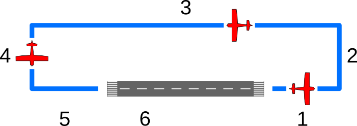
The Traffic Pattern is a standard route all aircraft must follow when near an airport, either taking off or landing. The traffic pattern has four stages (or “legs”), shown in Figure 9.16. The “downwind” mentioned above refers to one of these, the one with the number 3.
Most patterns at left-handed, i.e. all turns are to the left, as described above. Right-hand patterns also exist, and are marked as “RP” on the sectional. ATC will also advise you what pattern is in use.
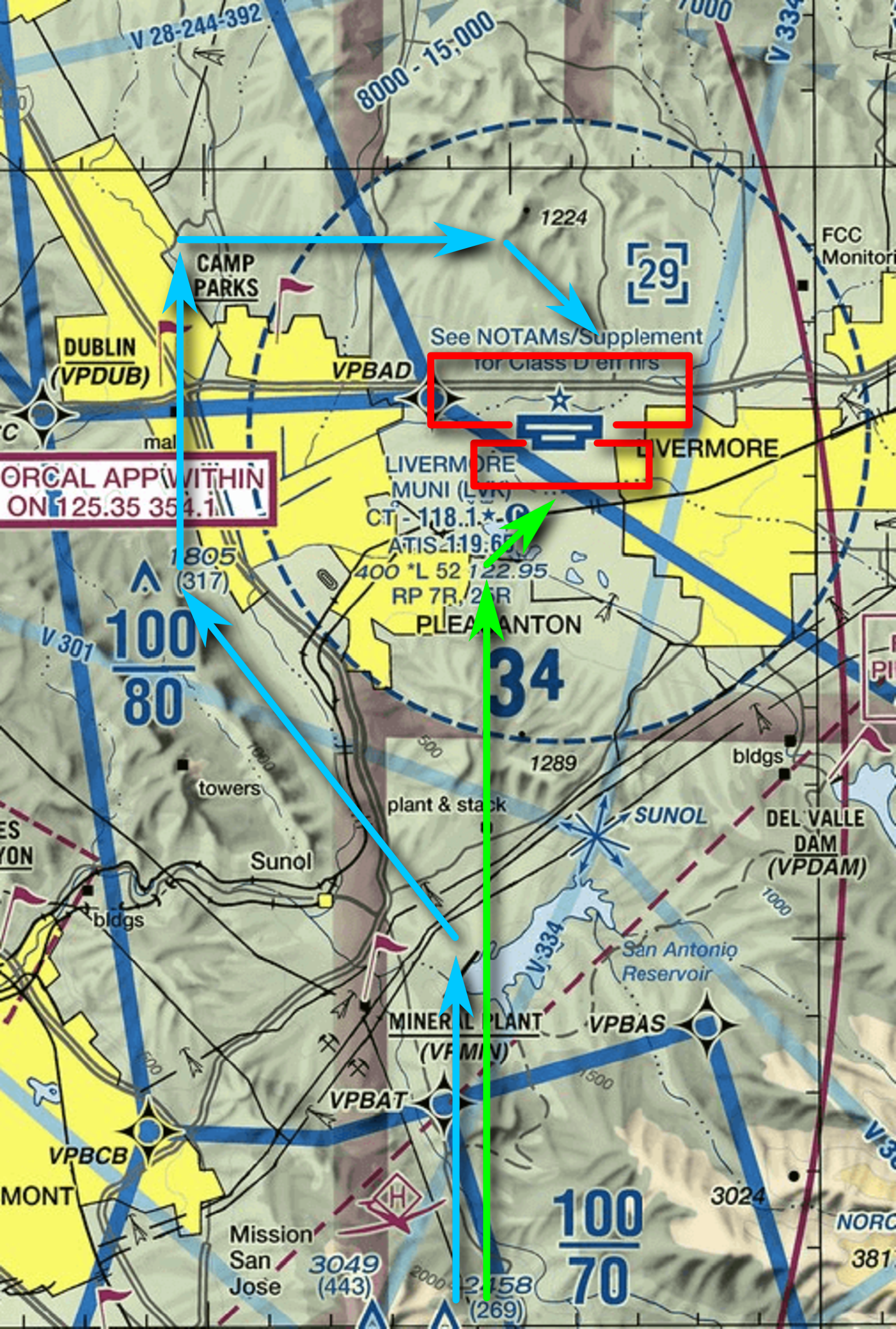
We’re approaching Livermore airport from the South, while the runways align East to West. Due to the prevailing Westerly wind, we’ll usually be directed to either runway 25R or 25L. 25R uses a right-hand pattern, while 25L uses a left-hand pattern. Both the patterns are illustrated in Figure 9.17. Depending on the runway we’ve been assigned, we’ll approach the airport in one of two ways. If we’ve been asked to land on runway 25R, we’ll follow the blue line in the diagram. If we’ve been asked to land on runway 25L, we’ll follow the green line.
We also need to reduce our altitude. We want to end up joining the pattern at pattern altitude, about 1000 ft AGL (Above Ground Level). Livermore airport is at 400 ft ASL (Above Sea Level), so we need to descend to an altitude of 1400 ft ASL.
We want to begin our maneuvers well before we reach the airport. Otherwise we’re likely to arrive too high, too fast, and probably coming from the wrong direction. Not the best start for a perfect landing :).
So, let’s start descending immediately.
Use your location relative to the airport and the two towns of Pleasanton and Livermore to navigate yourself to the appropriate pattern as shown in the figure 9.17.
Once you’re established on the downwind leg, you’ll need to report to ATC again. Do this in the same way as before. They will then tell you where you are in the queue to land. “Number 1” means there are no planes ahead of you, while “Number 9” means you might want to go to a less busy airport! They’ll also tell you who is ahead of you and where. For example “Number 2 for landing, follow the Cessna on short final” means that there is a single aircraft in front of you that is currently on the final leg of the pattern. When they land and are clear of the runway, they’ll tell ATC, who can then tell you “Number 1 for landing”.
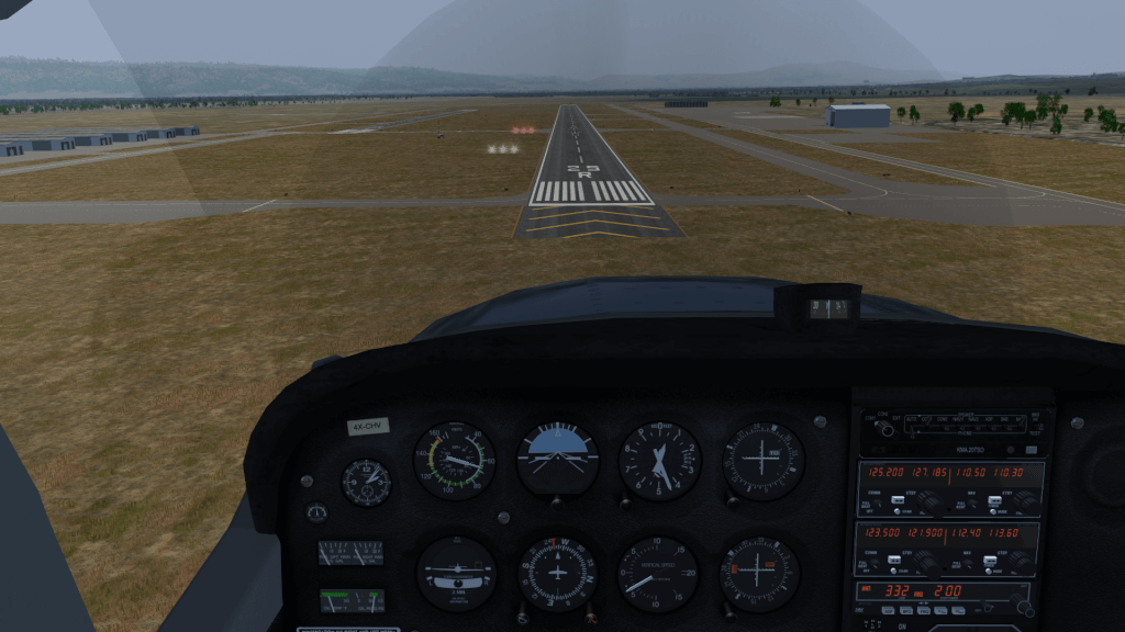
Once on final, you’ll notice two sets of lights on the left of the runway (enhanced in Figure 9.18). This is the VASI (Visual Approach Slope Indicator) and provides a nice visual clue as to whether you’re too low or too high on approach. Each set of lights can either be white or red. White means too high, red means too low. White and red together means just perfect. On a Cessna approaching at 60 kts, a descent rate of about 500 fpm should be fine. If you are too high, just decrease power to increase your descent rate to 700 fpm. If you are too low, increase power to decrease your descent rate to 200 fpm.
If for some reason it looks like you’re going to mess up the landing you can abort the landing and try again. This is called a “Go Around”. To do this:
Once you’re on the ground, you should taxi off the runway, then tell ATC you are clear. At high-altitude airports, you would lean the engine to avoid fouling the spark-plugs with an over-rich mixture. Find somewhere nice to park, shut down the engine by pulling mixture to full lean, then throttle off and magnetos to off (knob on the bottom left of the panel). Switch off the avionics master switch, tie down the aircraft, then go get that hamburger!
I hope this tutorial is of some use. If you have any comments, please let me know at stuart_d_buchanan {at} yahoo.co.uk.